https://answers.opencv.org/question/87583/detach-blobs-with-a-contact-point/


一、问题描述
带
有接触点的斑点时遇到问题,需要从上图中区分出每一个物件。最后能够得到类似这样的结果:
二、难点分析
简单2值化后会发现主要存在2个问题:1个是存在粘连的情况; 1个是目标物体不是全部一样的,有两个洞的情况、有一个洞的情况。
三、可行建议
1、A basic idea based on morphological operations and distance transformation(
代码1)
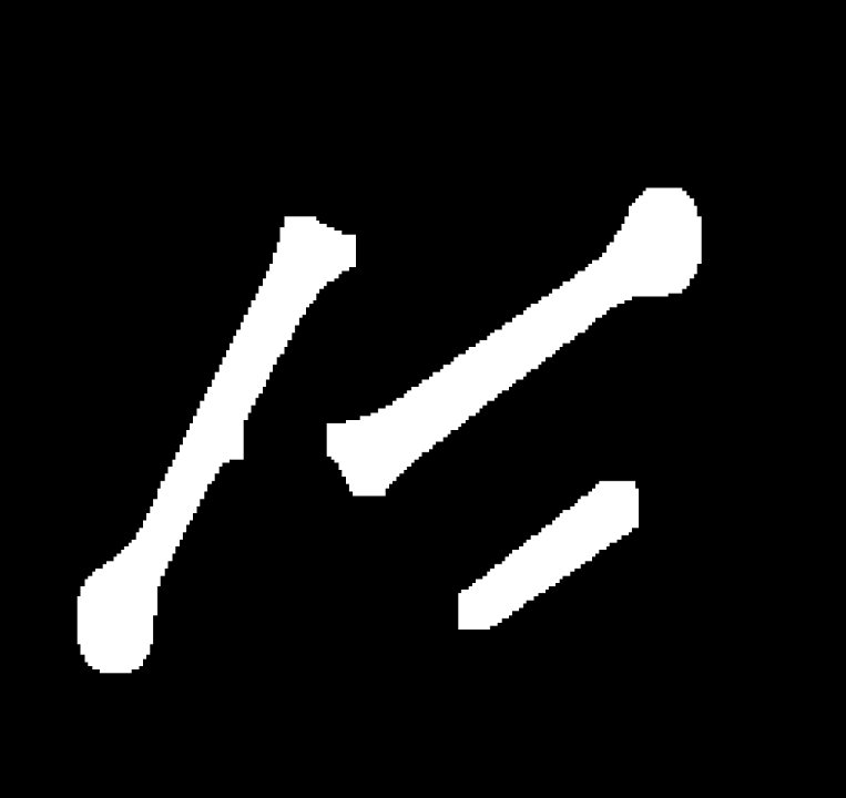
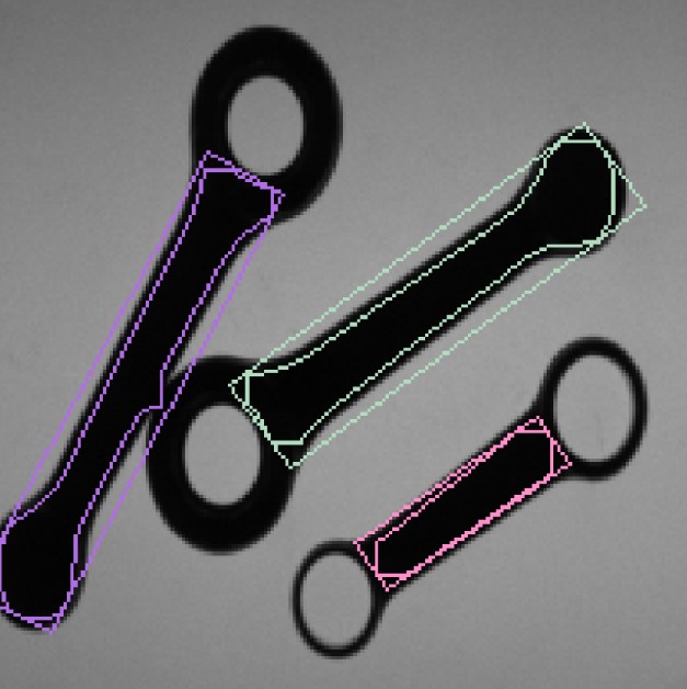
主要是通过距离变化,能够将这三个物件区分开来,虽然解决了粘连问题,但是在形态学变化的过程中,孔洞的信息丢失掉了;虽然可以使用findblobs等方法找到孔洞,但是孔洞和物件之间的连接信息也肯定会丢掉。
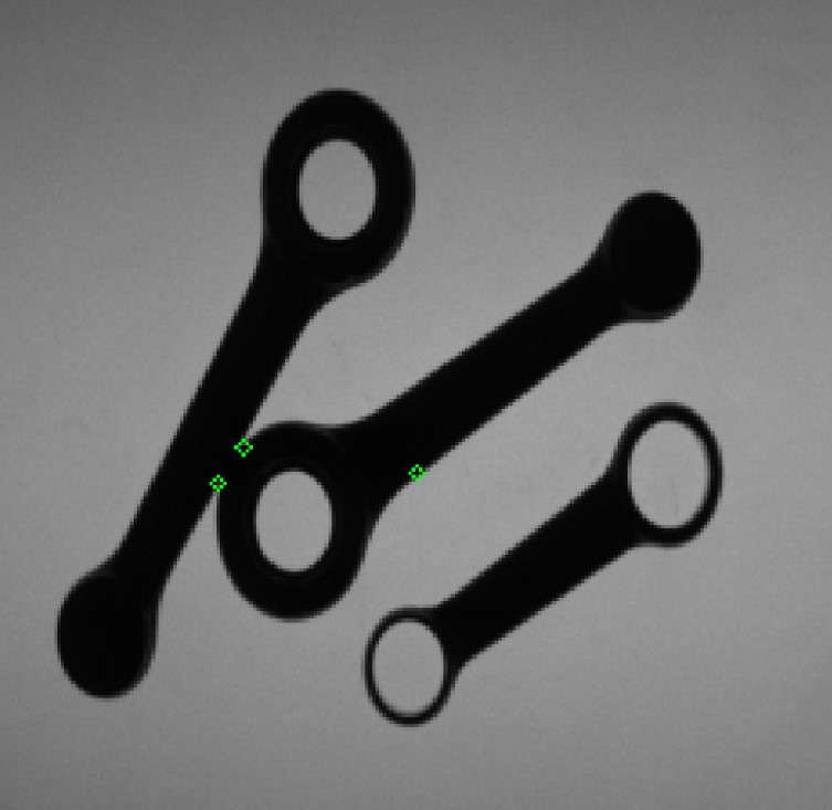
2、基于凸性缺陷的试用代码为您提供了一些关键点(代码2)
3、它进一步进行了优化(代码3)
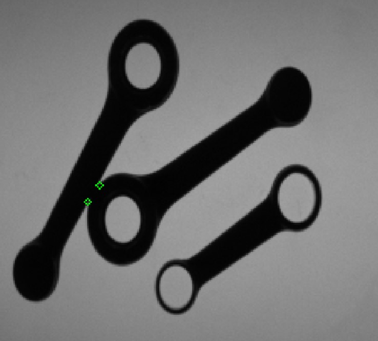
这里就是能够将缺陷的部分给检测出来了,方便后面进行分割。
四、小结反思
这个例子并没有给出完整的解答,最大的价值在于说明了“通过轮廓缺陷检测的方法解决粘连问题”的思路和方法。
代码1:
#
include
"pch.h"

#
include
<iostream
>

#
include
<string
>

#
include
<cstring
>

#
include
<cstdlib
>

#
include
<vector
>

#
include
"gocvhelper.h"
using
namespace std;
using
namespace cv;
//2020年11月8日10:26:09
//ssd 流水线文件
int main(
int argc,
char
*argv[])

{
// Load your image

    cv
:
:Mat src
= cv
:
:imread(
"e:/template/twoblobs_1.bmp");
// Check if everything was fine
if (
!src.data)
return
-
1;
// Show source image

    cv
:
:imshow(
"src", src);
// Create binary image from source image

    cv
:
:Mat gray;

    cv
:
:cvtColor(src, gray,COLOR_BGR2GRAY);
//cv::imshow("gray", gray);
// Obtain binary image

    Mat bw;

    cv
:
:threshold(gray, bw,
40,
255, cv
:
:THRESH_BINARY_INV
|cv
:
:THRESH_OTSU);

    cv
:
:imshow(
"bin", bw);
// Erode a bit

    Mat kernel
= Mat
:
:ones(
3,
3, CV_8UC1);

    erode(bw, bw, kernel);
//imshow("erode", bw);
// Perform the distance transform algorithm

    Mat dist;

    distanceTransform(bw, dist, cv
:
:DIST_L2,
5);
// Normalize the distance image for range = {0.0, 1.0}
// so we can visualize and threshold it

    normalize(dist, dist,
0,
1., NORM_MINMAX);

    imshow(
"distTransf", dist);
// Threshold to obtain the peaks
// This will be the markers for the foreground objects

    threshold(dist, dist, .
5,
1., cv
:
:THRESH_BINARY);
// Dilate a bit the dist image, this can be optional since in
// other use case might cause problems. Here though it works quite well

    Mat kernel1
= Mat
:
:ones(
5,
5, CV_8UC1);

    dilate(dist, dist, kernel1, Point(
-
1,
-
1),
2);

    imshow(
"peaks", dist);
// Create the CV_8U version of the distance image
// It is needed for findContours()

    Mat dist_8u;

    dist.convertTo(dist_8u, CV_8U);
// Find total markers

    vector
<Vec4i
> hierarchy;

    vector
<vector
<Point
>
> contours;

    findContours(dist_8u, contours, hierarchy, cv
:
:RETR_TREE,cv
:
:CHAIN_APPROX_SIMPLE);
// Find the rotated rectangles

    vector
<RotatedRect
> minRect(contours.size());
for (size_t i
=
0; i
< contours.size(); i
++)

    {

        minRect[i]
= minAreaRect(Mat(contours[i]));

    }

    RNG rng(
12345);
for (size_t i
=
0; i
< contours.size(); i
++)

    {

        Scalar color
= Scalar(rng.uniform(
0,
255), rng.uniform(
0,
255), rng.uniform(
0,
255));
// contour

        drawContours(src, contours,
static_cast
<
int
>(i), color,
1,
8, vector
<Vec4i
>(),
0, Point());
// rotated rectangle

        Point2f rect_points[
4]; minRect[i].points(rect_points);
for (
int j
=
0; j
<
4; j
++)

            line(src, rect_points[j], rect_points[(j
+
1)
%
4], color,
1,
8);

    }
/* From here you can extract the orientation of each object by using
    * the information that you can extract from the contours and the
    * rotate rectangles. For example, the center point, rectange angle, etc...
    */

    cv
:
:imshow(
"result", src);

    waitKey(
0);
return
0;

}
代码2:
#
include
"pch.h"

#
include
<iostream
>

#
include
<string
>

#
include
<cstring
>

#
include
<cstdlib
>

#
include
<vector
>

#
include
"gocvhelper.h"
using
namespace std;
using
namespace cv;
//2020年11月8日10:26:09
//ssd 流水线文件
int main(
int argc,
char
*argv[])

{
// Load your image

    cv
:
:Mat src
= cv
:
:imread(
"e:/template/twoblobs_1.bmp");
if (src.empty())
return
-
1;

    Mat bw;

    cvtColor(src, bw, COLOR_BGR2GRAY);

    bw
= bw
<
60;
// Find contours

    vector
<vector
<Point
>
> contours;

    vector
<
int
> contoursHull;

    vector
<Vec4i
> defects;

    findContours(bw, contours, RETR_EXTERNAL, CHAIN_APPROX_NONE);
for (size_t i
=
0; i
< contours.size(); i
++)

    {
if (contourArea(contours[i])
>
500)

        {

            approxPolyDP(contours[i], contours[i],
9,
true);
//多边形拟合

            convexHull(contours[i], contoursHull,
true);
//寻找凸包

            convexityDefects(contours[i], contoursHull, defects);
//计算缺陷
for (size_t j
=
0; j
< defects.size(); j
++)

            {

                Vec4i defpoint
= defects[j];

                circle(src, contours[i][defpoint[
2]],
2, Scalar(
0,
255,
0),
1);

            }

        }

    }

    imshow(
"result", src);

    waitKey();
return
0;

}
代码3:
#
include
"pch.h"

#
include
<iostream
>

#
include
<string
>

#
include
<cstring
>

#
include
<cstdlib
>

#
include
<vector
>

#
include
"gocvhelper.h"
using
namespace std;
using
namespace cv;
//2020年11月8日10:26:09
//ssd 流水线文件
int main(
int argc,
char
*argv[])

{
// Load your image

    cv
:
:Mat src
= cv
:
:imread(
"e:/template/twoblobs_1.bmp");
if (src.empty())
return
-
1;

    Mat bw;

    cvtColor(src, bw, COLOR_BGR2GRAY);

    bw
= bw
<
60;
// Find contours

    vector
<vector
<Point
>
> contours;

    vector
<
int
> contoursHull;

    vector
<Vec4i
> defects;

    findContours(bw.clone(), contours, RETR_EXTERNAL, CHAIN_APPROX_NONE);
for (size_t i
=
0; i
< contours.size(); i
++)

    {
if (contourArea(contours[i])
>
500)

        {

            approxPolyDP(contours[i], contours[i],
2,
true);

            convexHull(contours[i], contoursHull,
true);

            convexityDefects(contours[i], contoursHull, defects);
for (size_t j
=
0; j
< defects.size(); j
++)

            {

                Vec4i defpoint
= defects[j];

                Point pt
= contours[i][defpoint[
2]];
// get defect point

                Rect r3x3(pt.x
-
2, pt.y
-
2,
5,
5);
// create 5x5 Rect from defect point
// maybe no need but to be sure that the rect is in the image

                r3x3
= r3x3
& Rect(
0,
0, bw.cols, bw.rows);
int non_zero_pixels
= countNonZero(bw(r3x3));

                cout
<< non_zero_pixels
<< endl;
if (non_zero_pixels
>
17)

                    circle(src, contours[i][defpoint[
2]],
2, Scalar(
0,
255,
0),
1);

            }

        }

    }

    imshow(
"result", src);

    waitKey();
return
0;

    waitKey();
return
0;

}
代码4
Here's the code for the axes and the curve:
// Drawing orientation angle
float angle
=
-rod.orientation;
float length
= rod.length
/
5;

ellipse(image, rod.barycenter, Size(rod.length
/
6,rod.length
/
6),
0,
0,
-rod.orientation, Scalar(
0,
0,
255));

Point2f P2;

P2.x
=  (rod.barycenter.x
+ length
* cos(angle
* CV_PI
/
180.
0));

P2.y
=  (rod.barycenter.y
+ length
* sin(angle
* CV_PI
/
180.
0));

arrowedLine(image, rod.barycenter, P2, Scalar(
255,
255,
255));

P2.x
=  (rod.barycenter.x
+ length
* cos(
0));

P2.y
=  (rod.barycenter.y
+ length
* sin(
0));

arrowedLine(image, rod.barycenter, P2, Scalar(
0,
0,
255));